Tool Room
Custom Injection Mold Making — Production Tool Built by the People Who Run It
Two-plate to multi-cavity production tools in P20–S136, textured and slide-equipped, DFM-checked before steel — cut, tried and proven on the molding line it will live on.
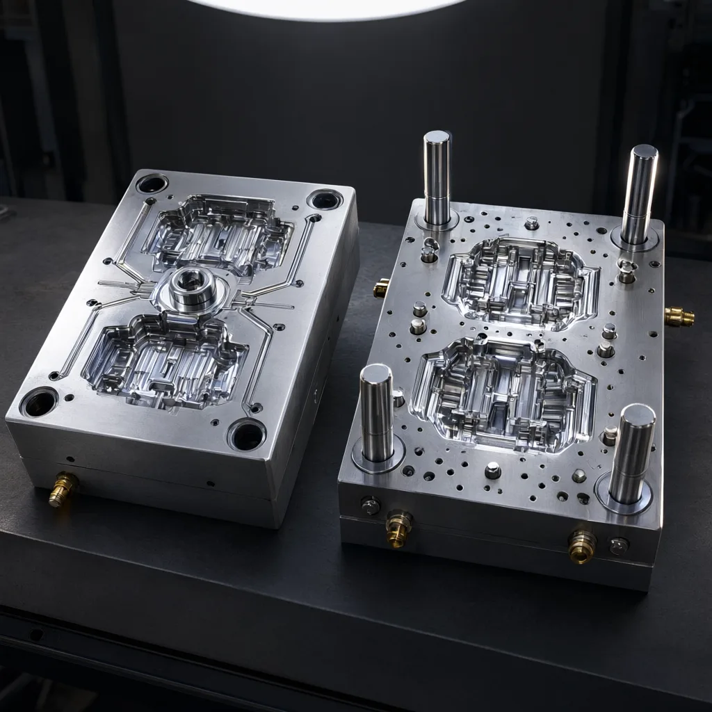
The mold is the product for the first 30 days — get the steel right and the parts take care of themselves. MOMAKING's tool room cuts injection molds for our own molding cells and for customers who ship tools to molders worldwide. Two-plate and three-plate tools, family and multi-cavity sets, slides and lifters, vents and parting lines that survive a million openings: this is a production tool room attached to a production molding line, and the difference shows in what gets designed away before the first cut.
Tool Classes We Build
- Single-cavity production tools: the honest default — one part, hardened where it wears, polished where it shows.
- Multi-cavity balanced sets: 2–16+ cavities with runner balance checked before steel; dimensional matching across cavities is part of the acceptance, not a hope.
- Family tools: when volumes align; when they don't, we say so at DFM because an unbalanced family tool wastes a molding cell forever.
- Side-actions: internal lifters, external slides, unscrew actions for threaded parts — designed with the molder's cycle in mind.
- Texture-ready faces: NAK80 and S136 for EDM texture (VDI 12/24/30…), polish grades SPI A1–A3.
Steel Selection, Plainly
P20 for straightforward, high-volume friendly cores and cavities; 718H pre-hardened for stability in larger sets; NAK80 where EDM texture and mirror polish live; S136 stainless for corrosive resins (flame-retarded, PVC-route, glass-filled grades) and long-life polish faces. Hardened inserts on wear slides and shutoffs. The steel spec is on the tool quotation line by line — you approve it before we cut, and the certified mill record travels with the tool documentation.
DFM: Where the Money Is Saved
Every tool quote passes a DFM pass that checks wall uniformity, draft (we ask for 1° minimum, more on deep textures), sink over bosses, witness-line risk on slides, and gate positions against your cosmetic surface list. Filling/pack/warp simulation is optional for the simple tools and near-mandatory for long-flow, thin-wall or optical parts — a two-hour study routinely prevents a welded-insert rework that costs ten times the study.
You receive the marked-up 3D: red where steel will not behave, green where the proposal saves cost. Sign it, or argue it with us — the tool model follows your decision, and everything stays versioned in the order system.
Tool Lead Time and Trials
Standard tools run 20–45 working days from signed tool design: simple single-cavity at the fast end, multi-cavity with textured faces and lifters at the long end. Weekly photos come from the EDM and assembly benches, so the process is visible, not a black box. T1 trials run on our press pool in your agreed resin; 5–10 shots ship free with a shot video and a dimensional layout. Corrective steel edits follow your comment sheet; re-trial until you sign the PPAP-style approval, then the tool moves to the production lane.
Ship the Tool, Keep the Relationship
Tools are crated with desiccant and VCI, export-labeled, and shipped worldwide on request — many customers take the tool to their regional molder after we prove it here. We maintain stored tools for returning programs, and the process documentation (temps, cycle, drying spec, AQL plan) is released with the tool. Molding a part is a commodity; proving a tool is the service.
Send STEP and target annual volume to the quote page, or ask the hard questions first: opheliamyers221@gmail.com / WhatsApp +1 315-623-3808.
Frequently Asked Questions
What steel and life will my tool get?
Can you match a sample or existing part?
Do you provide mold flow analysis?
What happens if T1 parts are out of tolerance?
Gate Design: Position, Type and Why It's a Cosmetic Decision
Melt enters your part somewhere, and that somewhere is written into the part forever. Edge gates are cheap and direct, but leave a witness at the parting line — which is why they land on hidden faces as house rule. Submarine (banana) gates shear off below the parting line during ejection and hide their tail under a flange or inside a boss cavity — the default for consumer shells where the exterior must stay clean and no trimming is wanted. Tab/film gates spread the flow into a thin tongue before the part, killing jetting marks and orienting molecular flow along a cosmetic span — the price is a tab to trim. Hot-tip point gates land wherever geometry wants (center of a disk, top of a boss) and self-remove with the runner system — but every tip is a heat zone, a drool risk and a maintenance item, priced into both the tool and the cycle plan. Behind all four sits the fill pattern the simulation names: weld lines where two fronts kiss (never place them where the part sees a screw torque), air traps at blind-fill corners (where burns live), and orientation-induced warp along the last-filled wall. This is why gate placement arrives in the DFM as a marked model, not after steel: your cosmetic face list argues with the melt front once, here, instead of at ten thousand parts when the witness mark appears mid-shelf.
Ejector Layout and Part Deformation: The Ugly Art Done Politely
Ejection is the phase where parts get damaged if it's designed wrong: pins push where material is thick and ribs run, push pins leave shallow circles on A-surfaces (so pins land on ribs, bosses and internal geometry — never a visible face), lifters coax sidewalls inward first, and the push-plate option wraps the whole part skirt for deep draws where pins alone would dim a bucket. Draft is the silent partner of every successful ejection — 1° on a texturized surface is a negotiation with friction and 3° is a handshake; a texture spec is therefore also an ejection spec, and a deep-draw sidewall with 0.5° draft on a leather grain is how a $30,000 tool earns its weekend repair reputation. Our DFM marks every face with its draft and its texture side by side for exactly that coupling, and the mold-flow report's ejection-force estimate says whether the layout you signed is physics or hope. Parts that stick anyway (undercut-heavy TPE, aggressive grain) get an honest tool feature added early: air poppets or a stripper plate — priced now, not at 2 a.m. during the pilot run.
The DFM and flow-study offers above are priced at zero and delivered within the standard 24-hour quote window — the cheapest place in the program to change a million-shot decision.
The Tool Documentation Package: What Ships With the Steel
A mold is delivered as a document set as much as a steel set, and the contents are the audit trail: the signed tool design (2D layout, 3D model, gate/vent/ejector map with the revision history showing every agreed change), the steel spec sheet with mill certificates for cavity/core inserts, the assembly drawing and part list for your maintenance shop, the T1/T2 shot records (resin lot, barrel profile, cycle times, first-shot dimensions), your approval samples' measurement layout, and the process data sheet that lets any competent molder run your tool in a week (drying spec, melt and mold temps, injection profile, cooling plan, cycle targets) — with the honest caveat that our process was tuned on our clamp, and any other press re-trials the window. If your current supplier will not release the process sheet with the tool, that tells you how they keep you chained to their press: our tool documentation belongs to you at the moment the tool does, no conversation, no ransom fee. Ask any tooling supplier for a sample documentation package before you sign; the quality of that binder predicts the quality of the steel.
Get this part priced
Upload your STEP file - AI quote in seconds, engineer-verified quote within 24 hours.